- 您现在的位置:买卖IC网 > Sheet目录3889 > PIC16C58B-04/SS (Microchip Technology)IC MCU OTP 2KX12 20SSOP
PIC18F2450/4450
DS39760A-page 156
Advance Information
2006 Microchip Technology Inc.
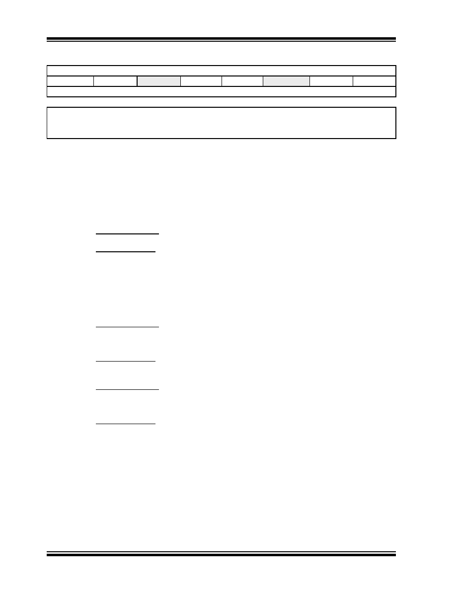
REGISTER 15-3:
BAUDCON: BAUD RATE CONTROL REGISTER
R/W-0
R-1
U-0
R/W-0
U-0
R/W-0
ABDOVF
RCIDL
—
SCKP
BRG16
—
WUE
ABDEN
bit 7
bit 0
Legend:
R = Readable bit
W = Writable bit
U = Unimplemented bit, read as ‘0’
-n = Value at POR
‘1’ = Bit is set
‘0’ = Bit is cleared
x = Bit is unknown
bit 7
ABDOVF: Auto-Baud Acquisition Rollover Status bit
1
= A BRG rollover has occurred during Auto-Baud Rate Detect mode (must be cleared in software)
0
= No BRG rollover has occurred
bit 6
RCIDL: Receive Operation Idle Status bit
1
= Receive operation is Idle
0
= Receive operation is active
bit 5
Unimplemented: Read as ‘0’
bit 4
SCKP: Synchronous Clock Polarity Select bit
Asynchronous mode:
Unused in this mode.
Synchronous mode:
1
= Idle state for clock (CK) is a high level
0
= Idle state for clock (CK) is a low level
bit 3
BRG16: 16-Bit Baud Rate Register Enable bit
1
= 16-bit Baud Rate Generator – SPBRGH and SPBRG
0
= 8-bit Baud Rate Generator – SPBRG only (Compatible mode), SPBRGH value ignored
bit 2
Unimplemented: Read as ‘0’
bit 1
WUE: Wake-up Enable bit
Asynchronous mode:
1
= EUSART will continue to sample the RX pin – interrupt generated on falling edge; bit cleared in
hardware on following rising edge
0
= RX pin not monitored or rising edge detected
Synchronous mode:
Unused in this mode.
bit 0
ABDEN: Auto-Baud Detect Enable bit
Asynchronous mode:
1
= Enable baud rate measurement on the next character. Requires reception of a Sync field (55h);
cleared in hardware upon completion.
0
= Baud rate measurement disabled or completed
Synchronous mode:
Unused in this mode.
发布紧急采购,3分钟左右您将得到回复。
相关PDF资料
PIC16F724-E/P
IC PIC MCU FLASH 4KX14 40-DIP
PIC16LF1827-I/SO
IC MCU 8BIT 4KB FLASH 18SOIC
PIC16F1827-I/SO
IC PIC MCU FLASH 4K 18-SOIC
PIC16LF1827-I/SS
IC MCU 8BIT 4KB FLASH 20SSOP
PIC16F1827-I/SS
IC PIC MCU FLASH 4K 20-SSOP
PIC12C508-04/P
IC MCU OTP 512X12 8DIP
22-15-3153
CONN FFC/FPC 15POS .100 RT ANG
PIC16F1826-I/MV
IC PIC MCU FLASH 2K 28-UQFN
相关代理商/技术参数
PIC16C58B-04E/P
功能描述:8位微控制器 -MCU 3KB 73 RAM 12 I/O RoHS:否 制造商:Silicon Labs 核心:8051 处理器系列:C8051F39x 数据总线宽度:8 bit 最大时钟频率:50 MHz 程序存储器大小:16 KB 数据 RAM 大小:1 KB 片上 ADC:Yes 工作电源电压:1.8 V to 3.6 V 工作温度范围:- 40 C to + 105 C 封装 / 箱体:QFN-20 安装风格:SMD/SMT
PIC16C58B-04E/SO
功能描述:8位微控制器 -MCU 3KB 73 RAM 12 I/O RoHS:否 制造商:Silicon Labs 核心:8051 处理器系列:C8051F39x 数据总线宽度:8 bit 最大时钟频率:50 MHz 程序存储器大小:16 KB 数据 RAM 大小:1 KB 片上 ADC:Yes 工作电源电压:1.8 V to 3.6 V 工作温度范围:- 40 C to + 105 C 封装 / 箱体:QFN-20 安装风格:SMD/SMT
PIC16C58B-04E/SS
功能描述:8位微控制器 -MCU 3KB 73 RAM 12 I/O RoHS:否 制造商:Silicon Labs 核心:8051 处理器系列:C8051F39x 数据总线宽度:8 bit 最大时钟频率:50 MHz 程序存储器大小:16 KB 数据 RAM 大小:1 KB 片上 ADC:Yes 工作电源电压:1.8 V to 3.6 V 工作温度范围:- 40 C to + 105 C 封装 / 箱体:QFN-20 安装风格:SMD/SMT
PIC16C58B-04I/P
功能描述:8位微控制器 -MCU 3KB 73 RAM 12 I/O RoHS:否 制造商:Silicon Labs 核心:8051 处理器系列:C8051F39x 数据总线宽度:8 bit 最大时钟频率:50 MHz 程序存储器大小:16 KB 数据 RAM 大小:1 KB 片上 ADC:Yes 工作电源电压:1.8 V to 3.6 V 工作温度范围:- 40 C to + 105 C 封装 / 箱体:QFN-20 安装风格:SMD/SMT
PIC16C58B-04I/P
制造商:Microchip Technology Inc 功能描述:IC 8BIT CMOS MCU 16C58 DIP18
PIC16C58B-04I/SO
功能描述:8位微控制器 -MCU 3KB 73 RAM 12 I/O RoHS:否 制造商:Silicon Labs 核心:8051 处理器系列:C8051F39x 数据总线宽度:8 bit 最大时钟频率:50 MHz 程序存储器大小:16 KB 数据 RAM 大小:1 KB 片上 ADC:Yes 工作电源电压:1.8 V to 3.6 V 工作温度范围:- 40 C to + 105 C 封装 / 箱体:QFN-20 安装风格:SMD/SMT
PIC16C58B-04I/SS
功能描述:8位微控制器 -MCU 3KB 73 RAM 12 I/O RoHS:否 制造商:Silicon Labs 核心:8051 处理器系列:C8051F39x 数据总线宽度:8 bit 最大时钟频率:50 MHz 程序存储器大小:16 KB 数据 RAM 大小:1 KB 片上 ADC:Yes 工作电源电压:1.8 V to 3.6 V 工作温度范围:- 40 C to + 105 C 封装 / 箱体:QFN-20 安装风格:SMD/SMT
PIC16C58B-20/P
功能描述:8位微控制器 -MCU 3KB 73 RAM 12 I/O RoHS:否 制造商:Silicon Labs 核心:8051 处理器系列:C8051F39x 数据总线宽度:8 bit 最大时钟频率:50 MHz 程序存储器大小:16 KB 数据 RAM 大小:1 KB 片上 ADC:Yes 工作电源电压:1.8 V to 3.6 V 工作温度范围:- 40 C to + 105 C 封装 / 箱体:QFN-20 安装风格:SMD/SMT